Your project paid for a laser scan survey. The data is accurate, registered and sitting on a server. Yet the MEP contractor is still working from the old drawings, and the duct clash shows up during installation.
That's the gap most BIM managers know well. A scan-to-BIM workflow only pays off when the scan data keeps working after the model is built. This guide walks through each step, from capture to a verified model, and shows where teams usually lose the value of their scans.
Why are project teams still not using scan data effectively?
Most teams treat scan data as an input to modeling, not as a coordination tool. The point cloud goes to the modeler, the model goes to the project, and the scan quietly disappears from the workflow. Nobody checks the finished model against it, and nobody outside the BIM team can open it.
When you dig into why, the same reasons come up on almost every project:
- The data is too heavy to share. A registered scan set for a hospital wing or a plant room can run to hundreds of gigabytes. Moving it to designers, trades and site teams means hard drives, file transfers and long downloads.
- Only specialists can use it. Point clouds need desktop software and some training. Project managers, superintendents and trade partners usually don't have either.
- The model and the scan live in different places. Federated models sit in one environment, scans in another. Comparing them takes time, so it gets skipped when the schedule is tight.
- Findings don't travel. Even when someone spots a deviation, it ends up as a screenshot in an email. It never becomes a tracked issue that the right trade picks up.
- Deviations are found too late. Without a regular scan-vs-BIM check, the first sign of a problem is a clash on site, a prefabricated spool that doesn't fit, or rework nobody budgeted for.
The common thread: the workflow stops at "model delivered." The scan-to-BIM steps below are designed to carry on to "model verified," and to keep scan data in use through construction.
What is a scan-to-BIM workflow?
Scan-to-BIM is the process of turning laser scan data of an existing building or site into an accurate BIM model of its as-built condition. It's the standard starting point for renovations, retrofits, expansions and facility management, where the existing drawings rarely match what's actually there. Our article on scan-to-BIM services looks at the benefits and common challenges in more detail.
The workflow has a second half that often gets skipped: verification. A verified model has been compared back against the scan, with deviations measured, reviewed and either fixed or accepted within an agreed tolerance. That's the difference between a model that looks right and one your team can coordinate, fabricate and install against.
It also helps to separate two terms that get used interchangeably:
| |
Scan-to-BIM
|
Scan-vs-BIM
|
|
Goal
|
Build a model from existing conditions
|
Check a model against existing or built conditions
|
|
When
|
Before design and coordination
|
During modeling QA, construction and handover
|
|
Output
|
As-built BIM model
|
Deviations, issues, progress status
|
|
Typical owner
|
Modeling team
|
BIM manager or coordinator
|
A complete workflow uses both.
The scan-to-BIM workflow, step by step
- Define scope, LOD and accuracy before anyone goes on site. Agree which areas, systems and disciplines the model must cover, the level of development (LOD), and the measured accuracy you need (often expressed as a level of accuracy, or LOA). Write down the deviation tolerance the model will be checked against later. Skipping this step is the most common reason models get rejected at the end.
- Plan the capture. Choose the right tools for the space: terrestrial scanners for detail, mobile scanners for long corridors and large floors, drones for roofs and facades. Plan scan positions and control points so congested areas such as plant rooms and ceiling voids get enough coverage.
- Capture on site. Scan the agreed scope, and capture extra coverage where systems overlap. A missed area at this stage usually means a return visit later.
- Register and quality-check the scans. Stitch individual scans into one coordinated dataset in your registration software and check it against survey control. Export the registered result in an open format such as E57.
- Publish the data where the whole team can reach it. Upload the registered scans to a shared environment and organize them by building, level or zone. This is the step that decides whether the scan stays useful after modeling.
- Extract only what the modeler needs. Crop the scan by level, room or system instead of loading the whole dataset into the authoring tool. Smaller point clouds keep Revit responsive and make modeling faster. See how to distribute and export scan data for scan-to-BIM.
- Model the as-built conditions. Build the BIM model to the agreed LOD, using the cropped point cloud as the reference.
- Verify the model against the scan. Overlay the model on the scan, measure deviations against your tolerance, and log anything outside it (more on this below).
- Coordinate and close issues. Turn deviations into tracked issues assigned to the right discipline, fix or formally accept them, and record the outcome.
- Keep scanning through construction. Repeat capture at key milestones and compare new scans with the model to monitor progress and catch installation errors before the ceilings close. Our guide to construction progress monitoring walks through how that works.
Steps 1 to 7 produce a model. Steps 8 to 10 make it one you can trust.
How to verify a BIM model against scan data
Verification is where the BIM manager earns the project's trust, and it doesn't have to take weeks. A practical scan-vs-BIM check comes down to four moves.
Align first. The model and the scan need to share the same coordinate system. If they don't line up, every deviation you measure is meaningless. Check alignment on a few known features, such as structural columns or floor slabs, before looking at anything else. Cintoo's scan and model alignment guidance covers what to do when the two arrive in different coordinate systems.
Compare against a tolerance, not by eye. Set the tolerance you agreed in step 1, then let the comparison show where model and reality differ by more than that. A color-coded deviation map makes it obvious where to look. Scrolling through a point cloud hoping to spot problems doesn't scale past a single room. For more on why this check matters, read the value in comparing as-builts to BIM models.
Prioritize by consequence. A 30 mm deviation on a partition wall is a note. The same deviation on a riser that a prefabricated MEP module will connect to is a fabrication problem. Review the high-risk systems first: structure, MEP mains, penetrations and anything being prefabricated off site.
Record every finding as an issue. Each deviation outside tolerance should become an issue with a location, a screenshot or view, an owner and a status. Push those issues into the coordination platform the team already uses, so they get resolved instead of forgotten. Our guide to construction issue tracking goes deeper on this step.
The outcome is a model you can sign off with evidence, and a record of what was checked if anyone questions it later.
Where scan-to-BIM workflows break down
Most failures aren't technical. They happen at handoffs, when data moves between teams and tools.
|
Breakdown
|
What it looks like on the project
|
Fix
|
|
No agreed tolerance
|
The model is "done" but nobody can say if it's accurate enough
|
Set LOD, accuracy and tolerance in step 1 and put them in the BIM execution plan
|
|
Whole dataset loaded into Revit
|
Slow files, crashed sessions, modelers working on partial views
|
Crop by zone or system before export
|
|
Scan stays with the BIM team
|
Trades and site teams never see it and keep using old drawings
|
Publish to a browser-based viewer everyone can open
|
|
Verification skipped under time pressure
|
Deviations surface as clashes during installation
|
Make scan-vs-BIM a gate before coordination sign-off
|
|
Findings shared as screenshots
|
Issues get lost in email threads
|
Log deviations as tracked issues in the coordination platform
|
|
One scan, then nothing
|
The model drifts from reality as construction progresses
|
Rescan at milestones and compare with the model
|
If you recognize three or more of these on your current project, the problem isn't your modelers. It's how the scan data moves.
How Cintoo supports the scan-to-BIM workflow
Cintoo picks up after registration, at step 5, and stays with the project through verification and construction. The goal is simple: catch model-to-field deviations before they turn into a clash or rework.
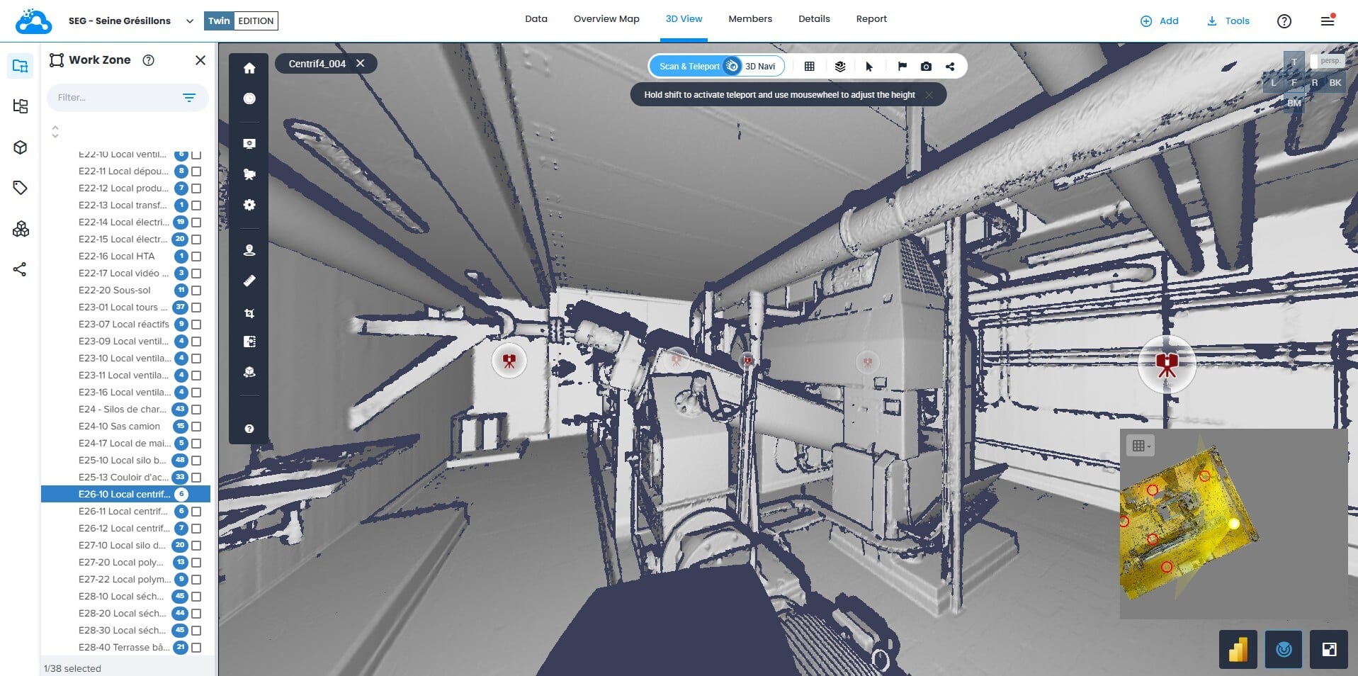
One place for scans and models. Upload registered scans (E57, RCP, LAS or LAZ) and Cintoo turns them into high-resolution 3D meshes. Bring in your BIM and CAD models alongside them, including RVT, IFC, NWD, NWC, DWG and DGN files. Everyone on the project streams the data in a desktop or laptop web browser, so trades and site teams can finally see the scan without installing anything.
Lighter files for modelers. Crop exactly the zone, level or system you need and send it to the modeling team as a point cloud.
Scan-vs-BIM in the browser. Manually align the scan and the model in Cintoo, then overlay the model on the as-built data and use the visual comparison tools to see where they differ.
Issues that reach the right people. Annotate deviations as notes or issues, assign them to team members and push them to your coordination platform. Here's how Cintoo fits into BIM coordination.
Progress you can measure. As construction moves on, compare new scans with the model. A Cintoo progress monitoring (Deviation Analysis) report calculates the difference between as-built and as-designed within a tolerance, including scan coverage per BIM element, and can feed Power BI dashboards. See 3D scan progress monitoring for how teams split runs by discipline or zone.
Two things worth knowing up front: Cintoo doesn't register scans, so that step stays in your registration software, and it isn't a BIM authoring tool. It's the shared environment between the two, where scan data gets used instead of archived. Compare capabilities on the Cintoo feature list.
To see the workflow on a live project, read how Hensel Phelps planned, built and managed a large construction project with Cintoo.
FAQ about Scan-to-BIM Workflow
How long does a scan-to-BIM project take?
It depends on the size of the site, the LOD and how congested the spaces are. Capture is usually the shortest part. Registration, modeling and verification take most of the time, and clear scope and tolerances up front shorten all three.
What file format should registered scans be delivered in?
E57 is the most widely used open format and works with most platforms. RCP is common in Autodesk-based workflows. Agree the format with the modeling team before capture.
What deviation tolerance should I use?
There's no single number. Tolerance depends on the system and what happens next: tighter for prefabricated MEP and structural connections, looser for finishes. Define it per discipline in the BIM execution plan.
Can I use scan-vs-BIM during construction, not just at the start?
Yes, and that's where it often saves the most. Comparing milestone scans with the model shows progress and catches installation errors while they're still cheap to fix.